In the process of inner hole rolling, the rolling elements (wheel roller, ball roller or pin roller) in the rolling device screw along the circumference of the surface of the processed hole wall, and exert a certain radial pressure on the processed hole wall. Under the rolling pressure of the rolling element, the inner hole of the workpiece produces elastic deformation (△Py) and plastic deformation (△P0). Plastic deformation not only changes the shape of the machined surface, but also changes its structure and physical properties. The irregularity peaks and valleys of the workpiece surface are ironed and filled, which reduces the surface roughness and improves the processing accuracy of the workpiece. The lattice of the rolled layer metal produces shear slip, severe distortion, elongation, fibrosis and breakage, which makes the structure become compact, the grains become finer, and the grain shape extends along the direction of maximum deformation. At the same time, compressive stress is produced in the metal surface, which strengthens the metal surface and improves the strength and hardness of the surface.
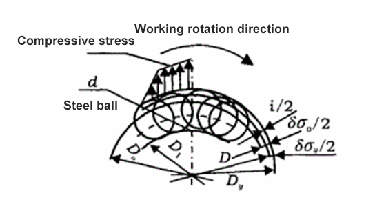
Deformation Diagram of Ball (Column) Rolling Inner Hole
This picture shows the deformation of the inner hole of the ball (column) rolling mill. The surface roughness of the inner hole is obviously reduced due to the plastic deformation of the surface metal of the hole wall caused by the rolling pressure of the rolling element.
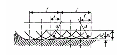
Axial rolling trace of steel ball on hole wall when rolling inner hole with ball roller burnishing tool
This picture shows the axial rolling trace of steel ball on the hole wall when rolling the inner hole with ball roller burnishing tool. The average height of roughness Rz is: within the basic length, from any line parallel to the midline of the contour, to the average distance between the five highest points (peaks) and the five lowest points (valleys) of the measured contour. Fig. F1 shows the center distance of the axially rolled tracks of two adjacent steel balls on the hole wall. If the roller burnishing tool distributes m steel balls on the circumference and the axial feed is f, then F1 = f/m. The average height reduction of roughness after rolling is Rz1.
Surface roughness of rolling parts is related to the intrinsic parameters of roller burnishing tools (diameter and number of balls) and the feed during rolling. Therefore, choosing ID roller burnishing tools with smaller diameter and larger number of steel balls and adopting smaller feed can make the surface roughness smaller after rolling.